Battery Performance Testing | Summary of Safety Performance Test Items for Lithium-Ion Batteries
With their high energy density, long cycle life, and low self-discharge rate, lithium-ion batteries have become the power source of choice for mobile electronics, electric vehicles, power tools, and energy storage systems. However, when exposed to mechanical abuse, electrical anomalies, or changes in the thermal environment, defects in structural design, protection strategies, or manufacturing processes can easily trigger safety incidents such as fire, explosion, and leakage, resulting in serious consequences including equipment damage and even personal injury. Therefore, establishing a systematic and comprehensive safety performance testing process for both cells and battery packs has become a necessary checkpoint throughout the entire process—from R&D design and pilot verification to mass shipment. By simulating various extreme conditions (such as nail penetration, overcharge, external short circuit, and thermal shock), safety testing not only verifies the robustness of the product design but also provides end customers with clear quality-assurance evidence; it is a key means to ensuring the safe controllability and compliant release of lithium-ion batteries.
1、Overview of Safety Performance Test Items
| No. | Test Item | Test Purpose | Acceptance Criteria (Summary) |
|---|---|---|---|
|
1 |
Nail penetration test |
Simulate internal short circuit |
Within the first 5 min: no smoke, no fire, no explosion; surface temperature ≤ 150 °C |
|
2 |
Continuous low-rate charging test |
Safety when left on the charger for a long time |
No fire, no explosion, no leakage. |
|
3 |
Overcharge test |
Tolerance to overcharge abuse |
No fire, no explosion. |
|
4 |
Overdischarge test |
Tolerance to reverse connection/forced discharge abuse |
No fire, no explosion. |
|
5 |
Room-temperature external short circuit |
Tolerance to external short circuit at room temperature |
No explosion, no open flame; case surface temperature < 150 °C. |
|
6 |
High-temperature external short circuit |
Tolerance to external short circuit at 55 ± 5 °C |
No explosion, no open flame; case surface temperature < 150 °C. |
|
7 |
Thermal shock test |
Risk of material shrinkage/short circuit at very high temperature |
No fire, no explosion. |
|
8 |
Combustion Test |
Evaluate fragment-ejection range under flame burning |
No component shall penetrate the aluminum mesh after the test. |
2、Detailed Explanations of Safety Performance Test Items
2.1 Nail Penetration Test
Test Purpose:
Simulate an internal short circuit in the cell.
Test Steps:
① Charge to full at 0.5C (use 1.0C for high-rate batteries) and rest for 1 h;
② Vertically drive a steel nail with a diameter of 2–3.5 mm through the center of the cell and keep it in place for at least 15 min; use a temperature data logger to record the battery surface temperature;
③ After the test is completed, let it rest for 1 h and observe the cell condition.
Acceptance Criteria:
Within the first 5 min of the nail penetration test, the cell shall not smoke, ignite, or explode; surface temperature ≤ 150 °C.

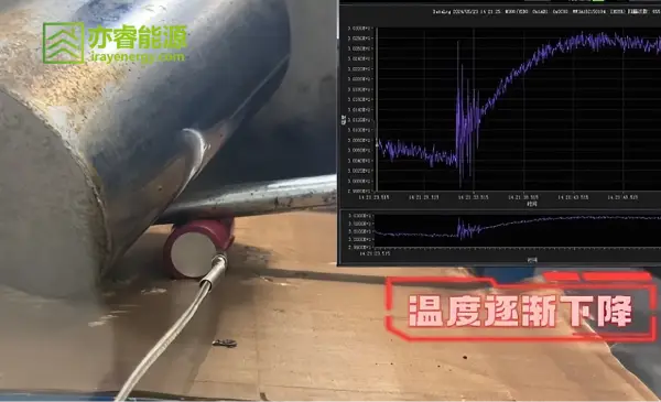
Figure 1. Battery undergoing nail penetration test
2.2 Continuous Low-Rate Charging Test
Test Purpose:
Simulate the safety of a cell left on the charger for an extended period during normal use.
Test Steps:
① Charge to full at 0.5C (use 1.0C for high-rate batteries);
② Rest for 1 h;
③ With the charge limit voltage set at a constant 4.200 V, continue charging at 0.05C constant current for 28 days.
Acceptance Criteria:
No fire, no explosion, no leakage.
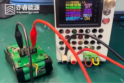
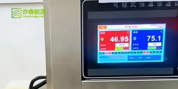
Figure 2. Battery undergoing continuous low-rate charging test
2.3 Overcharge Test
Test Purpose:
Evaluate the cell’s tolerance to overcharge.
Test Steps:
Iray Energy standard test steps (3C/4.6 V):
① At room temperature, discharge at 0.2C constant current to the cutoff voltage of 3.000 V;
② Charge at 3.0C current to 4.6 V; end the test when the cell charging time reaches 7 h or when the cell temperature drops to 20% of the temperature extreme.
IEC 62133 test steps (2C/5.9 V):
① At room temperature, discharge at 0.2C constant current to the cutoff voltage of 3.000 V;
② Charge at 2.0C current to 1.4 times the upper charging-voltage limit (but not exceeding 6.0 V); end the test when the upper voltage limit is reached.
UN38.3 test steps (2C/8.4 V):
① At room temperature, discharge at 0.2C constant current to the cutoff voltage of 3.000 V;
② Charge the battery at 2.0C constant current to 8.4 V, where 8.4 V is twice the cutoff voltage;
③ Conduct the test at ambient temperature, with a duration of 24 h.
Acceptance Criteria:
The cell shall not catch fire or explode.
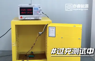
Figure 3. Battery undergoing overcharge test
2.4 Overdischarge Test
Test Purpose:
Simulate the performance of the cell or battery under reverse connection or abuse conditions.
Test Steps:
Iray Energy test steps:
① Fully discharge the cell at 1.0C;
② Reverse-connect the cell and charge at 1.0C constant current for 90 min.
UL38.3 standard procedures:
① Each battery must, at ambient temperature, be connected in series with a 12 V DC power supply and be forced to discharge at the rated maximum discharge current;
② For specially specified cases: the designated discharge current is the maximum current value of a circuit formed by connecting a resistor of specified size in series with the test battery. The forced-discharge duration for each battery shall equal its rated capacity divided by the initial test current.
UL1642 and UL2054 standard procedures:
① Combined battery packs are divided into two categories. Category 1: packs with only series and no parallel connections—the unit under test is a single cell. Category 2: packs with both series and parallel connections—the unit under test is a parallel cell string;
② Conduct the test at room temperature;
③ Sample preparation:
a) For batteries/packs equipped with overcurrent or temperature protective devices where these functions need to be tested, the devices shall remain connected; if their functions do not need to be tested, short these devices before the test;
b) Sample A shall be fully discharged, and Sample B shall be fully charged;
④ Short circuit: connect the fully discharged Sample A and Sample B in series with copper wire of maximum resistance 0.1 Ω to form a closed circuit for discharge;
⑤ Conditions for ending a single test: when a sample catches fire or explodes; or when one Sample A series battery pack reaches a fully discharged state (closed-circuit voltage ≤ 0.200 V), and the battery pack surface temperature returns to ambient temperature ±10 °C, while the circuit-closed duration is ≥ 90 min;
⑥ Use a new sample and repeat steps “①–⑤”.
Acceptance Criteria:
① Iray Energy standard: the cell shall not catch fire or explode;
② UN38.3 standard: the battery or cell shall show no disassembly and no combustion during the test and within 7 days after the test;
③ UL1642 standard: for samples where the functions of built-in protective devices are to be tested, if a protective device opens (open circuit), the test shall be repeated once; in each test the sample shall not catch fire or explode;
④ UL2054 standard: for samples where the functions of built-in protective devices are to be tested, the device components intended to act under discharge conditions shall trigger and the corresponding protection function shall activate upon the triggering condition; additionally, samples shall not catch fire or explode.
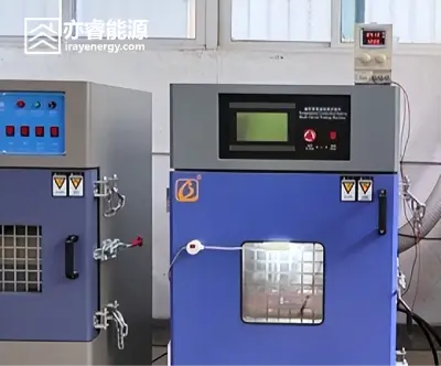
Figure 4. Battery undergoing overdischarge test
2.5 Room-Temperature External Short Circuit Test
Test Purpose:
Evaluate the ability of the cell or battery to withstand an external short circuit at room temperature.
Test Steps:
Each test sample must be fitted with a thermocouple to measure the surface temperature (the thermocouple junction is fixed at the center of the largest surface of the battery).
① After fully charging by the conventional charging method, place the sample in an explosion-proof chamber at 25 °C ± 5 °C;
② Place the thermocouple-equipped battery (junction fixed at the center of the largest surface) in a fume hood, directly short the positive and negative terminals, with a short-circuit lead/circuit resistance of (80 ± 20 mΩ); monitor the surface temperature of the battery during the test;
③ Stop the test when the battery temperature drops to about 20% below the peak value, or when the short-circuit duration reaches 24 h.
Acceptance Criteria:
a) No explosion and no open flame during and after the test;
b) Case surface temperature < 150 °C.
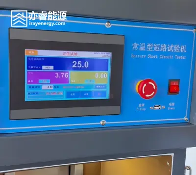
Figure 5. Battery undergoing room-temperature short-circuit test
2.6 High-Temperature External Short Circuit Test
Test Purpose:
Evaluate the ability of the cell or battery to withstand an external short circuit at a specified temperature.
Test Steps:
Each test sample must be fitted with a thermocouple to measure the surface temperature (the thermocouple junction is fixed at the center of the battery’s largest surface).
① After fully charging at 0.5C (use 1.0C for high-rate batteries), place the sample in an explosion-proof chamber at 55 °C ± 5 °C;
② Once the battery surface temperature reaches 55 °C ± 5 °C, rest for 30 min, then directly short the positive and negative terminals; the short-circuit lead resistance is (80 ± 20 mΩ). Monitor the battery surface temperature during the test;
③ Stop the test when the battery temperature drops to approximately 20% below the peak value, or when the short-circuit duration reaches 24 h.
Acceptance Criteria:
a) No explosion and no open flame during and after the test;
b) Case surface temperature < 150 °C.
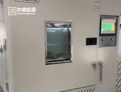
Figure 6. Battery undergoing high-temperature short-circuit test
2.7 Thermal Shock Test
Test Purpose:
Evaluate whether, at extremely high temperatures, the cell’s internal materials shrink or short-circuit, leading to fire or explosion.
Test Steps:
① Charge to full at 0.5C (use 1.0C for high-rate batteries);
② Place the cell in an air-circulating oven; raise the oven temperature at a rate of 5 ± 2 °C/min to 130 ± 2 °C;
③ When the temperature reaches 130 °C, start timing; maintain for 30 min, then stop the test.
Acceptance Criteria:
The cell or battery shall not catch fire or explode.
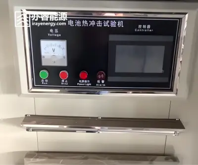
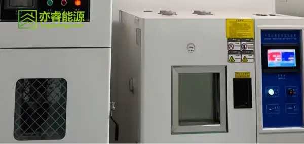
Figure 7. Battery undergoing thermal shock test
2.8 Combustion Test
Test Purpose:
Simulate whether, when the battery falls into a fire and is burned, the dispersion range of fragments from battery or cell explosion remains within a relatively safe area.
Test Steps:
Place the battery on the steel wire mesh of the test fixture. If the battery may slip off during the test, fix the sample to the mesh with a single piece of metal wire; if no such situation is expected, do not tie the battery. Heat the battery with a flame and stop heating when any of the following occurs:
a) The battery explodes;
b) The battery is completely burned;
c) Continuous heating for 30 min with no fire and no explosion.
Test equipment requirements: The diagonals of the top and bottom faces of the cage are 610 mm; cage height is 305 mm. The top face and side walls are made of aluminum mesh with wire diameter 0.25 mm, with 16–18 meshes per 25.4 mm (1 inch). The bottom face is made of steel wire mesh with wire diameter 0.43 mm, with 20 openings per 25.4 mm, and a central hole of 102 mm diameter.
Acceptance Criteria:
After the test, components constituting the battery (excluding dust-like products) or the entire battery shall not penetrate the aluminum mesh.
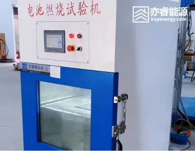
Figure 8. Battery undergoing combustion test
3、Referenced Standards and Applicable Specifications
The above safety performance tests are conducted with reference to the following industry standards:
- UL1642
- UL2054
- IEC62133
- GB/T 18287
- UN38.3
- Certain customer-specific standards
4、Summary and Recommendations
In the R&D and production of lithium-ion batteries, safety testing not only verifies the reliability of the materials system, structural design, and BMS, but is also directly related to whether the product can withstand abnormal scenarios in actual use—such as internal short circuit, overcharge/overdischarge, external short circuit, and extreme high temperatures—to prevent thermal runaway events. Especially in applications like mobile phones, power tools, and energy storage, once a battery fails it not only damages the equipment but may also endanger personal safety and brand reputation.
For products targeting overseas markets, test plans should be designed in advance with reference to mainstream certification standards such as UL, IEC, GB, and UN38.3. Only by running safety performance testing throughout the entire process—from design verification to mass-production release—can stable, safe, and reliable energy support be provided for end products, achieving a win–win of technological innovation and market expansion.